MVRC 2018 Rulebook
Revision 01, 08/07/2018
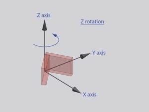
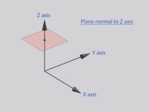
Longitudinal = X axis (+X = towards the rear)
Lateral/transverse = Y axis (+Y = towards the left when viewed from the front)
Vertical = Z axis (+Z = up)
FWCL = Front wheel centerline, RWCL = Rear wheel centerline
The reference plane is Z=0, which is coincident with the lowest surface of the allowed bodywork volume. The lowest point of the wheels is below the reference plane. The wheelbase of the car is fixed at 3000mm with the FWCL at X=0 and the RWCL at X=3000mm.
All supplied part files apply to one half of the car (the +Y side). The other side of the car must be a symmetric copy of this side. A full symmetric model must be submitted. Except where specified otherwise, any dimensions given apply to the entire car.
For CFD purposes, the center of gravity will be considered to be at 1.65m rearward of the FWCL. The optimum center of pressure will be near this value, depending on track.
Submissions:
You may submit an unlimited number of entries for a round at any time prior to the deadline, but only the most recent submission that was received prior to the deadline will be used. Alternatively, if you contact the MVRC organisers prior to the deadline, either by email or by submitting a text file through the normal entry submission method, you may:
- Nominate an entry from an earlier round of the same season to be re-used.
- Extend the submission deadline by two days. You may only do this once per season.
Introductory subclass:
A set of base bodywork is provided on the MVRC website. You may choose to compete in the “introductory subclass” by submitting only the parts that you wish to add to these standard parts. Please do not submit the supplied parts. These parts will be added to your submission before the compliance checks and the CFD simulation.
Participants in the introductory subclass will be ranked alongside full participants, but the introductory subclass champion will be the best-placed introductory subclass participant. You may move out of the introductory subclass and into the full championship at any point during the season, keeping the points earned so far, but you will no longer be eligible for the introductory subclass championship.
0.1
An entry should be a single compressed archive file (ZIP etc) named using the format “<team>_<round>_<version>”. It must contain:
- (only for full entries) In a directory named “special_bc”:
- (rule 4.2) Each engine inlet surface as a separate STL, with a filename starting with “engine_in”
- (rule 4.3) Each engine exhaust surface as a separate STL, with a filename starting with “exhaust”
- (only for full entries) In a directory named “monitoring_surfaces”:
- (rule 4.1) Each heat exchanger monitoring surface as a separate STL (front face of heat exchanger translated rearward along its normal by 30mm)
- (only for full entries) In a directory named “porous_media”:
- (rule 4.1) Each heat exchanger extrusion as a separate STL
- In a directory named “high_res_surfaces”:
- (rule 3.2) Rear wing
- (rule 3.4) Thin elements inside the rear diffuser
- (optional) Some or all bodywork forward of the FWCL, excluding the front fenders
- In a directory named “vehicle_body”: All remaining bodywork.
- Introductory subclass: do not include the supplied bodywork.
These parts should be exported as separate STL files with 1 unit = 1m. The unit setting may be verified by opening the STL file in ParaView and checking “bounds”.
0.2 (ignored for introductory subclass)
A plain text file must be included in the archive to specify the offset for the following parts compared to their position as supplied in the parts file, even if they have not been moved, stating the following:
- Front suspension templates Z-offset in mm
- Footbox template Z-offset in mm
- Vehicle rake in deg
0.3
Only the parts specified in rule 0.1 and the text file in rule 0.2 should be included. No other guide parts should be submitted. Please avoid including internal construction geometry. The combined size of the STL files (before compression) must be below 80MB for ASCII STL, or below 20MB for binary STL. Introductory subclass: 40MB for ASCII STL, 10MB for binary STL.
1.1
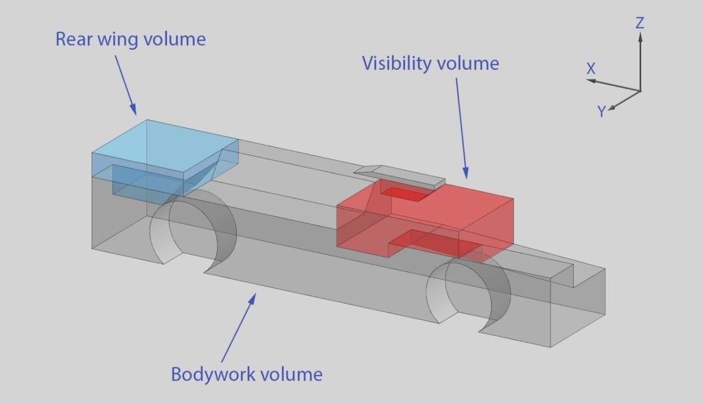
All modeled geometry is considered as bodywork unless otherwise specified. No bodywork is allowed outside the bodywork volume unless otherwise specified.
1.2
No part of the bodywork may be less than 10mm thick. See appendix 1 for the exceptions to this rule.
1.3
- The intersection of all individual bodywork parts must form a single watertight solid with no holes.
- It is recommended that each individual part also forms a watertight solid with no holes.
If the simulation fails because a part is not watertight, the MVRC staff reserve the right to issue a penalty or reject the entry.
2.1
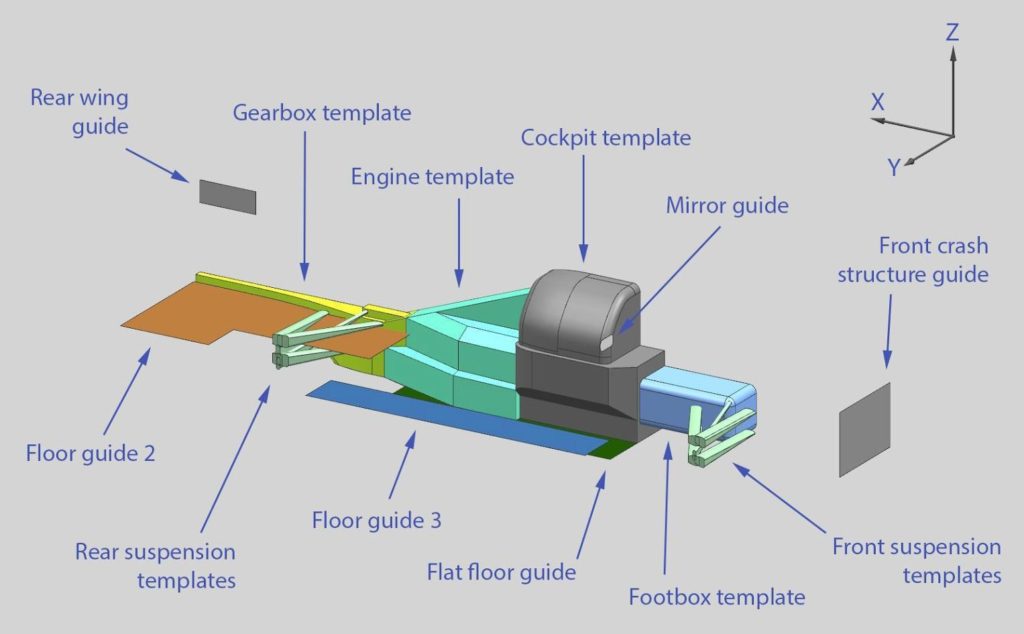
All supplied parts must not be moved, rotated or altered, with the following exceptions:
- The footbox template may be moved vertically no more than ±100mm from its supplied position (upwards until the top face is level with the ledge on the cockpit template, or downwards until the bottom face is on the reference plane).
- Supplied front suspension templates may be moved (as a group) no more than 100mm upwards or 50mm downwards from their supplied position.
Introductory subclass: no adjustment allowed. The front suspension and footbox are both fixed at +100mm.
2.2
The vehicle may be rotated between -1.25 and 0 deg around the Y-Axis.
2.3 (ignored for introductory subclass)
Bodywork must completely enclose these provided parts:
- Cockpit template
- Engine template
- Gearbox template
- Footbox template
2.4
No bodywork is permitted inside the visibility volume except the following:
- Surfaces of the cockpit which would form the windows and A-pillars. This area should form a smooth continuous shape, no separate window surfaces.
- Rear view mirrors, their mountings and their fairings. Mountings and fairings which clearly impede cockpit vision, or which are made larger than structurally necessary so as to produce downforce, will be judged to be illegal.
Introductory subclass: no extra bodywork may be placed inside the visibility volume.
2.5 (ignored for introductory subclass)
Bodywork covering the wheels:
- For this rule, the phrase ‘wheel volume’ refers to the entire volume inside the wheel wells of the supplied bodywork volume.
- As viewed from above, no part of any wheel volume may be visible. This requirement is ignored in areas more than 950mm from the car centerline.
- As viewed from the front, no part of the front wheel volumes may be visible. This requirement is ignored in areas more than 950mm from the centerline of the car or less than 50mm above the reference plane.
2.6 (ignored for introductory subclass)
Bodywork surrounding suspension parts:
- As viewed from above and from the front, no part of the front suspension templates may be visible.
- As viewed from above, no part of the rear suspension templates may be visible.
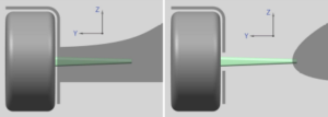
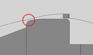
2.7
- The inner end of each suspension template must lie inside the volume formed by bodywork. Any such bodywork must form a realistic load path to the chassis, being at least 25mm thick.
- There must be only one intersection between each template and the surface of the bodywork:
- either the suspension template must lie fully inside bodywork, except for the outer end which protrudes from the bodywork to meet the wheel (left),
- or, the inner end of the suspension template must lie inside the central bodywork, with no other bodywork intersecting the suspension template (right).
3.1 (ignored for introductory subclass)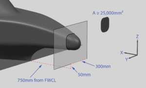
- The front crash structure must be attached to the bodywork covering the cockpit templates to provide a realistic load path.
- The intersection of bodywork with the front crash structure guide (a plane 750mm forward of the FWCL, only considering areas less than 300mm from the car centerline and more than 50mm above the reference plane) forms one or more closed shapes. The shape(s) must be at least 25000mm2 in total area. The shape(s) must each be at least 100mm high/wide at any point (measuring perpendicular to the boundary).
- As the plane forming this intersection is moved rearwards towards the cockpit, the load-bearing region(s) must not diminish below the 25000mm2 minimum and must remain at least 100mm high/wide (measuring perpendicular to the boundary).
Structurally unrealistic designs will be judged to be illegal.
3.2 – Rear wing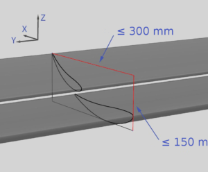
- No bodywork is permitted inside the the rear wing volume other than:
- Rear wing profiles
- An endplate on each end
- Up to 2 pieces of bodywork whose sole purpose is to attach the rear wing profiles to the bodywork
- When referred to from elsewhere, “endplate” and “attachments” are defined as bodywork inside the rear wing volume only. The continuation of these parts beyond the rear wing volume is considered as normal bodywork.
- Any intersection of the rear wing profiles with a plane normal to the Y-axis must form either 1 or 2 closed sections. The entirety of these sections must fit into a rectangle of 300mm (X-axis) by 150mm (Z-axis). The included rear wing guide is a rectangle with these dimensions.
- The rear wing must be attached to the bodywork by at least 2 points. Endplates may be used as attachments. The attachments must be separated by at least 350mm in the Y-axis, and must provide a realistic load path to the body of the car.
- When viewed from the rear, at any vertical position inside the rear wing volume, each endplate must not span more than 25mm in the Y-axis.
- It is permissible to not use any rear wing profiles. In this case, there should be no bodywork inside the rear wing volume.
3.3 – Floor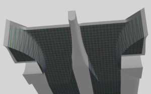
- Covering the entire area specified by the flat floor guide there must be a flat, unbroken surface lying on the reference plane.
- Any bodywork visible from below, which lies directly above/below floor guide 2, excluding the parts inside the rear wing volume, must be no more than 270mm above the reference plane.
- Any bodywork visible from below, which lies directly above/below floor guide 3, must be no more than 125mm above the reference plane.
- When any bodywork specified in this rule is intersected with any plane normal to the X or Y axes, there must be no gaps in any of the sections formed (considering only one side of the car). Surfaces inside the diffuser which are vertical will be considered to be visible from below. The engine exhaust outlet surfaces are ignored for this requirement. A small tolerance will be allowed in the area surrounding the wheel well.
3.4
After having met all other rules, thin bodywork elements (turning vanes / fences, no thicker than 25mm) may be added inside the rear diffuser and below floor guide 3, provided that these elements remain within the boundaries of the car when viewed from below. Any such elements must be submitted as separate parts, placed in the high_res_surfaces directory.
3.5
One rear view mirror each side is mandatory:
- The reflective surface must be 150mm wide (Y-axis) and 75mm high (Z-axis), with a 25mm radius fillet at each corner. A guide is included for this area.
- The reflective surface must be positioned within the visibility volume, and more than 400mm from the car center line.
- The reflective surface must be planar, facing directly rearward, and must be fully visible from the rear of the car, ignoring the parts in the rear wing volume.
The reflective surface is then considered as bodywork.
Introductory subclass: the mirrors are included with the supplied bodywork.
Mandatory inlet/outlet surfaces
The ability to provide adequate airflow for cooling and engine inlets/outlets is calculated from the airflow analysis rather than being enforced in the regulations. Designs unable to meet the nominated airflow requirements will have reduced engine performance. See appendix 2 for these requirements.
Introductory subclass: the heat exchanger, engine inlet and engine exhaust surfaces are included with the supplied parts for reference. Please do not include these with your submission.
4.1 – heat exchanger
There must be one heat exchanger each side of the car:
- Each heat exchanger is made up of a single planar shape extruded rearward along its normal by a distance of 60mm.
- The planar shapes may be rotated around the Y-axis only. Any such rotation must be no more than 60 degrees from a forward-facing orientation.
- Each shape must be at least 180,000mm2 in area.
- Each shape must be no more than 600mm wide (Y-axis).
- Each shape must be no more than 500mm high (Z-axis) when the shape is in a directly forward-facing orientation (i.e. before any rotation).
- The heat exchanger extrusion must be located entirely inside the bodywork volume and must not intersect any bodywork or templates, but it must touch the bodywork along its edges to provide a realistic mounting to the body of the car.
- As specified in rule 0.1, the following parts must be included with the submission as separate STLs:
- Each 60mm extrusion
- A copy of each planar shape translated rearward along its normal by 30mm (i.e. the mid-surface of the extrusion)
4.2 – engine inlet
Either 1 or 2 engine inlet surfaces are required (over the entire car), which:
- Must be planar surfaces with a combined area of at least 15,000mm2.
- Must be at least 50mm high/wide at any point (measuring perpendicular to the boundary).
- Must be located within the bodywork volume, and between a point 875mm rearward of the FWCL and a point 600mm forward of the RWCL.
- Must not be located in a region defined by the mid-surface of the heat exchanger (as defined in rule 4.1) extruded rearwards along its normal for 1000mm.
- May be rotated from a forward-facing orientation by no more than 30 degrees.
- The engine inlet inner templates are the volume(s) formed by an extrusion of each inlet surface rearward along its normal for a distance of 100mm. These templates must be entirely enclosed in bodywork and must not intersect any other parts or templates.
4.3 – engine exhaust
2 exhaust pipe outlet surfaces are required (over the entire car), which;
- Must be circular, planar surfaces, each between 5000mm2 and 5200mm2 in area.
- Must lie within the bodywork volume, and rearward of the rearward-most point of any of the following:
- A point 1000mm forward of the RWCL
- The heat exchanger
- Any engine inlet surface
- May be rotated from a rearward-facing orientation by no more than 30 degrees.
- The engine exhaust inner templates are the volumes formed by an extrusion of each exhaust outlet surface forward along its normal for a distance of 100mm. These templates must be entirely enclosed in bodywork and must not intersect any other parts or templates.
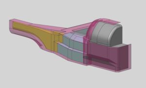
The engine inlet / exhaust surfaces should each be planar surfaces, not solids. The recommended format for the engine inlets and exhausts is as shown below. The surfaces should fit within a cavity in the bodywork so that the outer edges of the surfaces are touching the bodywork without any gap. The faces may extend slightly inside the bodywork, unless the area of the inlet / outlet / duct section is very close to the minimum allowed.

4.4 (ignored for introductory subclass)
There must be realistic paths inside the bodywork through which:
- Flow from the engine inlet(s) could reach the engine template.
- Flow from the engine template could reach the exhaust outlets. This path may pass between the rear suspension templates.
- Coolant lines could be run to connect the heat exchanger to the engine template
Other than where specified, these paths may not pass through the volume taken up by any of the supplied templates. In cases where the paths specified above would pass through the space between bodywork and the internal templates, bodywork in the relevant area may not be ‘shrink-wrapped’ around the internal templates. In these cases, to determine how much space should be left between the bodywork and the internal templates:
- In areas surrounding the cockpit, engine and gearbox templates, bodywork in the relevant area should remain outside the offset guide (below right).
- In other areas, enough space should be left along the path for a tube of approximately 35mm radius.
Appendix 1: 10mm thickness
- For front and rear wing parts, each wing element should be at least 10mm thick at some part along its chord (across the entire span). Problems may be encountered at the CFD meshing stage if the thickness remains very low over a long distance at the rear of the chord.
- For thin bodywork elements (plates, strakes / fences), once the 10mm thickness requirement is met, a sharp trailing edge and rounded leading edge (roughly circular in shape) are permitted. The 10mm thickness should be maintained over approximately ⅔ of the length or more, and must be maintained in any
- load-bearing region.
- For any gurney flap / wickerbill, a triangular section is permitted if the base width is at least 10mm and the height is no more than 5 times the base width.
- Thickness may be checked in Netfabb (free version), by opening an STL file, scaling by 1000, clicking ‘new measuring’ and using the ‘wall thickness’ option.
Appendix 2: airflow requirements for inlets and outlets
| Engine Intake |
|
| Engine Exhaust |
|
| Cooling |
|
Lap Time Prediction
Lap time prediction shall be performed by the Virtual Stopwatch application using the aerodynamic coefficients and characteristics of each car which are calculated by the CFD analysis program MantiumWFlow. The mechanical parameters of the car in Virtual Stopwatch are fixed throughout the season and summarised below:
- Total vehicle mass (including driver): 950kg Mass Distribution (F:R): 45:55
- Track Width: 1.64m Wheelbase: 3.0m
- Tyres: 365-18″ Slick, Soft Compound Engine: 3.0 litre, 540hp @ 12,000 rpm KERS: 2000kJ storage, 144bhp max output
- Gearbox: 8 Speed, Seamless Shift. (fixed ratios between 2:1 and 0.91:1) Final Drive: 3.2
- Suspension: Unequal length, double wishbone, push-rod front and rear.
With the baseline aerodynamic coefficients provided below, the performance of the vehicle shall be as per the following table:
| Cd.A = 1.3, Cl.A = 4.5, COP = 1.65m | +20% Drag and Downforce | -20% Drag and Downforce | |
| Nurburgring | 386.44s | -3.17s | +3.13s |
| Monaco | 84.31s | -0.75s | +0.75s |
| Silverstone | 104.92s | -1.33s | +1.33s |
| Sepang | 107.53s | +0.5s | -0.55s |
| Sao Paulo | 81.34s | +0.4s | -0.44s |
The competitor can test the performance of a car using Virtual Stopwatch throughout the season at any of the tracks listed above using the following link: http://www.competition-car-engineering.com/MVRC_Timing.htm .