
Rules ver 3.2
(Version 3.2 clarifications are highlighted)
1. Reference Positions and Datums:
Longitudinal = X axis (+X = towards the rear)
Lateral/transverse = Y axis (+Y = towards the left when viewed from the front)
Vertical = Z axis (+Z = up)
FWCL = Front wheel centerline, RWCL = Rear wheel centerline
The reference plane is Z=-300, which is coincident with the lowest surface of the allowed bodywork volume (Z=0 at FWCL). The lowest point of the wheels is below the reference plane. The wheelbase of the car is fixed at 3400mm with the FWCL at X=0 and the RWCL at X=3400mm.

2. Submission Requirements
2.1 An entry should be a single compressed archive file (ZIP etc) named using the format “<team>_<round>_<version>”. It must contain:
- In a directory named “special_bc”:
- (rule 6) One engine inlet surface, with a filename starting with “engine_in”
- [deleted]
- In a directory named “monitoring_surfaces”:
- (rule 4.1) Each heat exchanger monitoring surface as a separate STL (front face of heat exchanger translated rearward along its normal by 30mm)
- In a directory named “porous_media”:
- (rule 4.1) Each heat exchanger volume as a separate STL
- In a directory named “high_res_surfaces”:
- (rule 8) Parts inside of the barge board volume
- (rule 9) Front wing
- (rule 10) Rear wing
- (rule 11) Thin elements in the rear diffuser.
- (rule 11) Floor plank
- In a directory named “vehicle_body”: All remaining bodywork.
2.2 These parts should be exported as separate STL files with 1 unit = 1m. Note; files should be saved with suffix .stl (NOT .STL).
2.3 A full symmetric model must be submitted. Except where specified otherwise, any dimensions given apply to the entire car.
2.4 A plain text file must be included in the archive to specify the offset for the following parts compared to their position as supplied in the parts file, even if they have not been moved, stating the following:
- [Deleted]
- Vehicle rake in deg
- Predicted minimum lap time (see 2.7)
2.5 Only the parts specified in rule 0.1 and the text file in rule 0.2 should be included. No other guide parts should be submitted. Please avoid including internal construction geometry. The combined size of the STL files (before compression) must be below 80MB for ASCII STL, or below 20MB for binary STL.
2.6 An unlimited number of entries may be submitted for a round at any time prior to the deadline, but only the most recent submission that was received prior to the deadline will be used. If no submission is made the last submission from the previous round will be used automatically. Alternatively, contacting the MVRC organisers prior to the deadline, either by email or by submitting a text file through the normal entry submission method, it is possible to:
- Nominate an entry from an earlier round of the same season to be re-used.
- Extend the submission deadline by two days. This may only be done once per season.
2.7 Entrants have to submit a predicted minimum lap time. In case more than 15 cars enter a race, this lap time will be used to determine the 15 cars that will get simulated. If a car fails to beat the submitted time, it will get disqualified from the race and barred entry for the following race.
3. Internal Supplied Parts
3.1 The following supplied parts, in their supplied position, and without modification must be fully enclosed within the competitor’s model:
Note: The Gearbox has been moved to 4.1; the rearmost part of the gearbox lies outside of the legality volumes and must not be covered by bodywork.
- Safety Cell
- Engine
- Engine Intake Plenum
- Engine Cover Fin

4. External Supplied Parts
4.1 The following MVRC-supplied parts must be used in their supplied position, without modification. These parts are part of the CFD simulation:
- Helmet
- HALO
- Gearbox
- Floor
- Front and rear wheels
- Rear suspension
- Mirrors
- Front wing central neutral section
- Floor plank (located underneath floor)
- Exhaust out
- Front suspension
4.2 [Deleted]

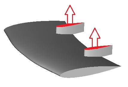
5. Heat Exchangers
5.1 There must be one heat exchanger on each side of the car, meeting the following rules:
- 5.1.1 Each heat exchanger is made up of a single planar shape extruded a distance of 60mm in a direction normal to it’s front face.
- 5.1.2 The planar shapes may be rotated around the Y-axis only. [deleted]
- 5.1.3 Each shape must be at least 180,000mm2 in area.
- 5.1.4 [deleted]
- 5.1.5 The heat exchanger extrusion must be located entirely inside the bodywork volume and must not intersect any bodywork or templates, but it must touch the bodywork along its edges to provide a realistic mounting to the body of the car.
- 5.1.6 As specified in rule 2.1, the following parts must be included with the submission as separate STLs:
- Each 60mm extrusion
- A copy of each planar shape translated rearward along its normal by 30mm (i.e. the mid-surface of the extrusion)
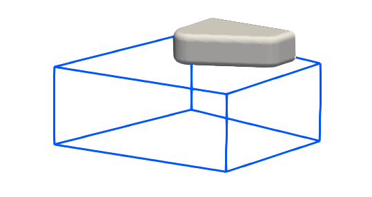
6. Power Unit Inlet
6.1 One engine inlet surface is required to be located above and behind the driver’s helmet on the car centreline, which:
- 6.1.1 Must be a planar surface with an area of at least 15,000mm2.
- 6.1.2 Must be at least 50mm high/wide at any point (measuring perpendicular to the boundary).
- 6.1.3 Must be located within the bodywork volume at a point 1540mm rearward of the FWCL, and 700mm above the reference plane.
- 6.1.4 The engine inlet inner templates are the volume(s) formed by an extrusion of each inlet surface rearward along its normal for a distance of 100mm. These templates must be entirely enclosed in bodywork and must not intersect any other parts or templates with exception of the engine intake plenum.
7. Power Unit Exhaust
7.1 200mm (or more) of the end of the Power Unit’s exhaust pipes must project outside of the car’s bodywork.

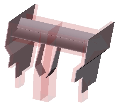
8. Bodywork – General
8.1 All bodywork must be fully contained within the supplied legality volumes.
8.2 Parts inside of the barge board volume must be included into the high_res folder.
8.3 No part of the bodywork may be less than 10mm thick. See appendix 1 for the exceptions to this rule.
8.4 The provided suspension parts may intersect the bodywork.

9. Front Wing
- 9.1 The competitor must use the supplied front wing central neutral section without modification.
- 9.2 The competitor must extend the two support elements up to the underside of their nose cone.
- 9.3 Front wing design is free, but must be fully contained within the supplied legality volumes.
10. Rear Wing
- 10.1 The car’s rear wing must be supported on two symmetrical vertical elements, connecting the rear wing to the car’s gearbox, located no more than 100mm from the car’s center line within the legality volume.
- 10.2 The rear wing support elements must each be >=10mm thick (Y-axis) and >=150mm long (X-axis)
- 10.3 Rear wing design is free, but must be fully contained within the supplied legality volumes.
- 10.4 Rear wing endplate design is free, but must be fully contained within the supplied legality volumes.
11. Floor and Diffuser
- 11.1 The MVRC floor part must be used.
- 11.2 The design of the diffuser is free, but must stay within the supplied legality volume.
- 11.3 Edge features may be added to the Step-plane floor within the supplied legality volumes.
- 11.4 The provided floor plank is located below the reference plane and is a mandatory part.
- 11.5 The MVRC-supplied floor and the floor plank are parts of the CFD simulation.

12. Wing Mirrors
- 12.1 The competitors must add wing mirror supports. The design is free but must remain within the legality volume.
13. Vehicle Rake
- 13.1 With the car constructed in accordance with rules 1 to 12, above, the entire car, excluding wheels , may be be rotated a maximum of –1 degrees (nose down), with the centre of rotation being located at X = 0mm, Z = 0mm.
- 13.2 The competitor must nominate the number of degrees in the supplied text file.
Appendix 1: 10mm thickness
A1.1 For front and rear wing parts, each wing element should be at least 10mm thick at some part along its chord (across the entire span). Problems may be encountered at the CFD meshing stage if the thickness remains very low over a long distance at the rear of the chord.
A1.2 For thin bodywork elements (plates, strakes / fences), once the 10mm thickness requirement is met, a sharp trailing edge and rounded leading edge (roughly circular in shape) are permitted. The 10mm thickness should be maintained over approximately ⅔ of the length or more, and must be maintained in any load-bearing region.
A1.3 For any gurney flap / wickerbill, a triangular section is permitted if the base width is at least 10mm and the height is no more than 5 times the base width.
Appendix 2: airflow requirements for inlets and outlets
| Engine Intake |
|
| Engine Exhaust |
|
| Cooling |
|
Appendix 3: Lap Time Prediction
Lap time prediction shall be performed by the Virtual Stopwatch application using the aerodynamic coefficients and characteristics of each car which are calculated by the CFD analysis program MantiumFlow. The mechanical parameters of the car in Virtual Stopwatch are fixed throughout the season and summarised below:
- Total vehicle mass (including driver): 740kg CG Position: 1.85m
- Overall Width: 2m Wheelbase: 3.4m
- Tyres: 12″fr, 16” Rr, Slick, Soft Compound
- Engine: 1.6l V6 Turbo with ERS.
- Gearbox: 8 Speed, Seamless Shift.
- Suspension: Unequal length, double wishbone, push-rod front and rear.
The performance of the cars can be determined from Virtual Stopwatch.