
Rules ver. 1.0
1. Reference Positions and Datums:
Longitudinal = X axis (+X = towards the rear)
Lateral/transverse = Y axis (+Y = towards the left when viewed from the front)
Vertical = Z axis (+Z = up)
FWCL = Front wheel centerline, RWCL = Rear wheel centerline
The reference plane is Z=0, which is coincident with the lowest surface of the allowed bodywork, excluding the floor plank. The wheelbase of the car is fixed at 3400mm with the FWCL at X=0 and the RWCL at X=3400mm.

2. Submission Requirements
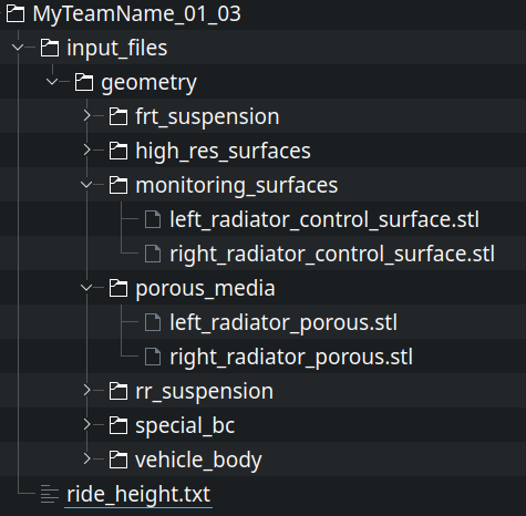
2.1 An entry should be a single compressed archive file (ZIP etc) named using the format “<team>_<round>_<version>”. It must contain a directory structure “input_files/geometry/“ which contains:
- A directory named “special_bc”:
- (rule 7) One engine inlet surface, with a filename starting with “engineIn”
- A directory named “monitoring_surfaces”:
- (rule 6) Each heat exchanger monitoring surface as a separate stl-file (front face of heat exchanger translated rearward along its normal by 30mm)
- A directory named “porous_media”:
- (rule 6) Each (left and right hand sides) heat exchanger volume as a separate stl file
- A directory named “high_res_surfaces” (rule 9.2).
- Directories “frt_suspension” and “rr_suspension” (rule 14).
- A directory named “vehicle_body”: All remaining bodywork.
2.2 These parts should be exported as separate stl files with 1 unit = 1m. Note: files must be saved with lower case suffix .stl (NOT .STL).
2.3 A full symmetric model must be submitted. Except where specified otherwise, any dimensions given apply to the entire car.
2.4 A plain text file must be included in the archive to specify the offset for the following parts compared to their position as supplied in the parts file, even if they have not been moved, stating the following:
- Vehicle rake in deg
- Vehicle ride height adjustment in mm
2.5 Only the parts specified in rule 2.1 and the text file in rule 2.4 should be included. No other guide or provided mandatory parts must be submitted. The combined size of the stl files (before compression) must be below 160MB for ASCII stl, or below 40MB for binary stl.
3. Mandatory Supplied Parts
3.1 The following supplied parts, in their supplied position, and without modification must be used in the CFD model, based on the supplied CAD file MVRC_2025_CAD_Parts_V*: If files are supplied in multiple formats, the stl files are in doubt the ones defining the relevant geometry.
- MAND-Halo_V*
- MAND-Helmet_and_cockpit_CFD_V*
- MAND-Helmet_and_cockpit_RenderingOnly_V*
- MAND-Hub_FL_V*
- MAND-Hub_FR_V*
- MAND-Hub_RL_V*
- MAND-Hub_RR_V*
- MAND-Mirrors_V*
- MAND-Monocoque_V*
- MAND-PU_Gearbox_V*
- MAND-RV-Planck_V*
- MAND-Suspension_FL_minimum_section_V*
- MAND-Suspension_FR_minimum_section_V*
- MAND-Suspension_RL_minimum_section_V*
- MAND-Suspension_RR_minimum_section_V*
- MAND-Wheel_FL_V*
- MAND-Wheel_FR_V*
- MAND-Wheel_RL_V*
- MAND-Wheel_RR_V*
4. Supplied Volumes
- RV_Suspension_cover_FL_V*
- RV_Suspension_cover_FR_V*
- RV_Suspension_cover_RL_V*
- RV_Suspension_cover_RR_V*
- RV-Bargeboards_V*
- RV-Chassis_V*
- RV_FBrake_duct_frt_V*
- RV_FBrake_duct_rr_V*
- RV-Floor_fence_V*
- RV-Floor_led_V*
- RV-Floor_V*
- RV-FW_Endplates_V*
- RV-FW_Profiles_V*
- RV-FW_Strakes_V*
- RV_Halo_envelope_V*
- RV-Mirrors_support_V*
- RV-Rear_Wing_Profiles_V*
- RV-Rear_Wing_V*
- RV-RW-Pylon_V*
- RV-Sidepods-EngCover_V*
- RV-Tail_V*
5. Supplied Reference Surfaces
- RS-EC_V*
- RS-Floor_board_V*
- RS-Floor_body_V*
- RS-Floor_foot_V*
- RS-Floor_mask_V*
- RS-Floor_ref_V*
- RS-Floor_step_V*
- RS-FW-profiles_V*
- RS-FWEP_side_V*
- RS-FWEP-bottom_V*
- RS-Nose_V*
- RS-RWEP_V*
6. Heat Exchangers
6.1 There must be one heat exchanger on each side of the car, meeting the following rules:
- 6.1.1 Each heat exchanger is made up of a single planar shape extruded a distance of 60mm in a direction normal to its front face.
- 6.1.2 The planar shapes may be rotated around the Y-axis only.
- 6.1.3 Each shape must be at least 140,000mm2 in area.
- 6.1.4 The heat exchanger extrusion must be located entirely inside the bodywork volume and must not intersect any bodywork or templates, but it must touch the bodywork along its edges to provide a realistic mounting to the body of the car.
- 6.1.5 As specified in rule 2.1, the following parts must be included with the submission as separate stl files:
- Each 60mm extrusion
- A copy of each planar shape translated rearward along its normal by 30mm (i.e. the mid-surface of the extrusion)
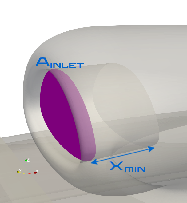
7. Power Unit Inlet
7.1 One engine inlet surface is required to be located above and behind the driver’s helmet on the car centreline, which:
- 7.1.1 Must be one planar surface with an area of at least 15,000mm2.
- 7.1.2 Must be entirely located within the bodywork volume at a point at least 1880mm rearward of the FWCL, and at least 725mm above the reference plane.
- 7.1.3 The engine inlet inner template is the volume formed by an extrusion of the inlet surface rearward along its normal for a distance of 100mm. This template must be entirely enclosed in bodywork and must not intersect any other parts or templates with exception of the engine intake plenum.
8. Power Unit Exhaust
8.1 The exhaust is made of two mandatory parts, the pipe on the geometry MAND_PU_Gearbox_V* and the surface MAND-Exhaust-Outlet-Surface_V*.
8.2 The volume inside of the tailpipe between exhaust out and the end of the exhaust pipe must remain unobstructed
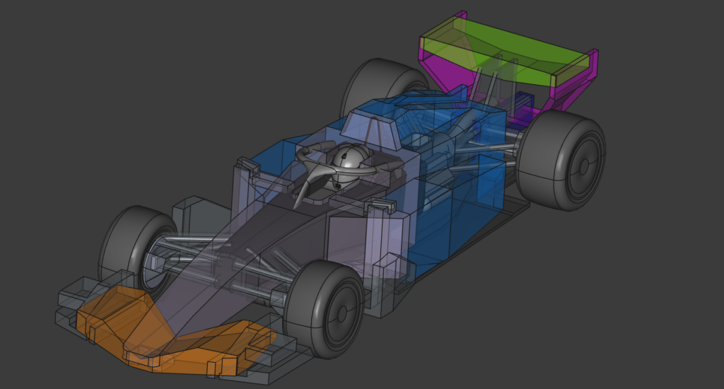
9. Bodywork – General
9.1 All bodywork must be fully contained within the supplied legality volumes. All body work must:
– 9.1.1 be fully contained within RV-BODY_V*
– 9.1.2 when looking from above, fully obscure RS-NOSE
– 9.1.3 when looking from the side, fully obscure RS-EC
9.2 Parts inside of the volumes:
RV-FW_*- RV_FW_Profiles_V*
- RV_FW_Strakes_V*
- RV_FW_Endplates_V*
RV-Rear_Wing_*- RV_Rear_Wing_V*
- RV_Rear_Wing_Profiles_V*
- RV_Halo_envelope_V*
- RV-Mirrors_support_V*
must be included into the high_res folder.
9.3 No part of the bodywork may be less than 10mm thick. See appendix 1 for the exceptions to this rule.
9.4 The provided suspension parts may intersect the bodywork.
9.5 All body parts, including the supplied parts, must be capable of forming a single body, connected by parts meeting rule 9.3. i.e. there should be no floating parts.
9.6 When intersected with any X-plane in the interval X = ( -1250 mm, 50 mm), not inside of RV-FW_*, must produce only up to one continuous closed section.

9.7 An intersection of an X-plane with parts inside of RV-Chassis_V* at X=-550mm must produce a face with a minimal area of 44,000mm².
9.8 Above Z=600mm and outside of Y=150mm, parts in the RV_Sidepods-EngCover_V* volume must create only 1 section when cut with any y plane.
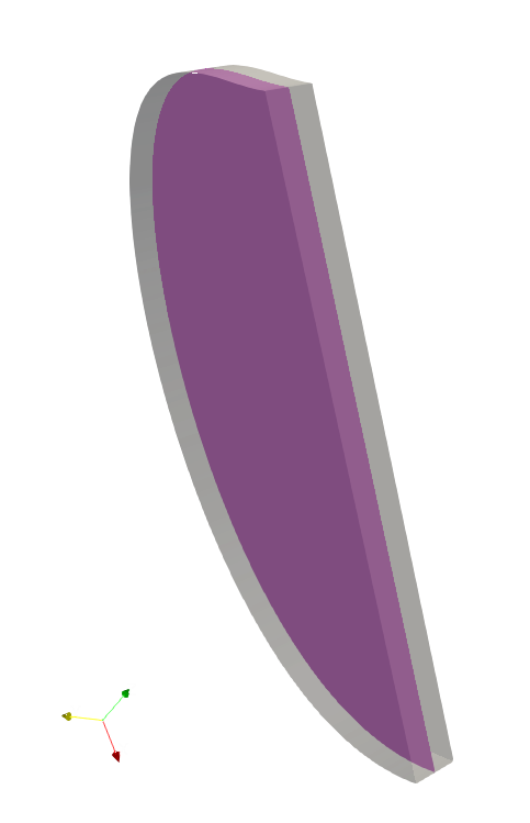
10. Frontwing
The frontwing consists of the following parts:
- fw_mainplane (non rotating profiles, inside RV-FW_Profiles_V*)
- fw_flaps (rotating profiles, inside RV-FW_Profiles_V*)
- fw_ep
- fw_strake
10.1 fw_mainplane must:
- be fully contained within RV-FW-PROFILES_V*
- when cut by any Y-plane in the interval Y=(0mm, 575mm) produce exactly one section.
10.2 fw_flaps must:
- be fully contained within RV-FW-PROFILES_V*
- when cut by any Y-plane in the interval Y=(0mm, 575mm) produce exactly two sections.
10.3 When combined, fw_mainplane and fw_flaps must:
- when viewed from above, fully obscure RS-FW-profiles_V*.
10.4 fw_ep must:
- be fully contained within RV-FW_Endplates_V*
- when viewed from the side, fully obscure RS-FWEP-SIDE_v*
- when viewed from below, fully obscure RS-FWEP-BOTTOM_v*
10.5 fw_strake must:
- be fully contained within RV-FW_Endplates_V*
- when cut by any Z-plane in the interval Z = (75mm, 200mm) produce up to 4 sections.
- when cut by any Y-plane in the interval Y = (450mm, 555mm) produce up to 2 sections.
11. Rear Wing
The rear wing consists of the following parts:
- rw_mainplane
- rw_flaps
- rw_ep
- rw_pylon
11.1 rw_mainplane must:
- be fully contained within RV-RW-PROFILES_V*
- when cut by any Y-plane in the interval Y=(0mm, 575mm) produce up to one section.
11.2 rw_flaps must:
- be fully contained within RV-RW-PROFILES_V*
- when cut by any Y-plane in the interval Y=(0mm, 575mm) produce up to two sections.
11.3 rw_ep must:
- be fully contained within RV-RWEP-BODY_V*
- when cut by any Y-plane in the interval Y=(345mm, 575mm) produce up to two sections
- when viewed from the side, fully obscure RS-RWEP_V*.
11.4 rw_pylon must:
- be fully contained within RV-RW-PYLON_V*
- when cut by any Z-plane in the interval Z=(450mm, 725mm) produce exactly two sections.
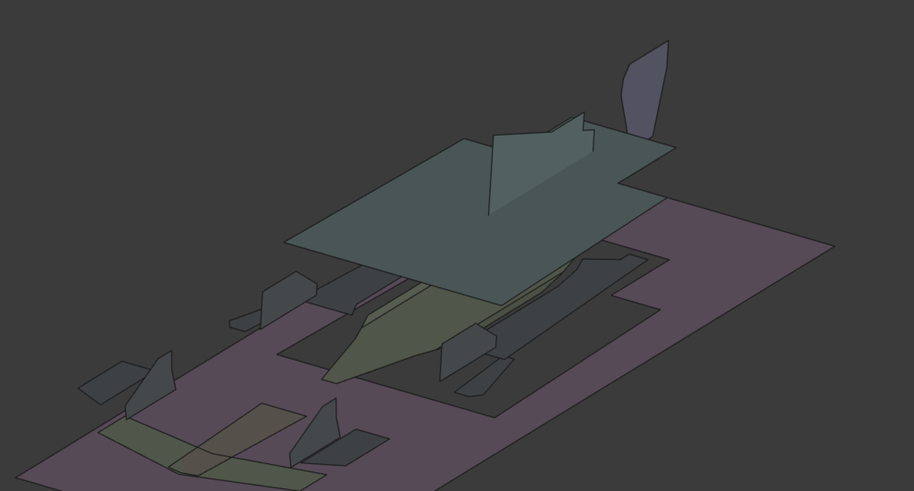
12. Floor
The floor consists of the following parts:
- floor_body
- floor_board
- floor_led (leading edge device)
- floor_fence
12.1 floor_body must:
- be fully contained within RV-Floor_V*
- when cut by any Z-plane in the interval Z = (35mm, 275mm) produce up to five sections.
- be fully visible from either above or below, such that any surface obscured from one direction is visible from the other
- when viewed from below, fully obscure:
- RS-FLOOR-STEP_V*,
- RS-FLOOR-REF_V*
- RS-FLOOR-BODY_V*
- when viewed from below, fully obscure parts pertaining to the body, when viewed through the hole of RS-FLOOR-MASK_V*
12.2 floor_board must:
- be fully contained within RV-FLOOR-BOARD_V*
- when viewed from the side, fully obscure RS-FLOOR-BOARD_V*
- when viewed from above, fully obscure RS-FLOOR-FOOT_V*
12.3 floor_led must
- be fully contained within RV-FLOOR-LED_V*
12.4 floor_fence must
- be fully contained within RV_FLOOR-FENCE_V*
13. Side Mirrors
All parts that make up the mirror body must:
13.1 be fully contained within RV-Mirrors_support_V01*
13.2 when cut by any Y-plane in the interval Y = ( 175 mm, 650 mm) produce up to one section.
13.3 when cut by any Z-plane in the interval Z =( 45 mm, 600 mm) produce up to two sections.
13.4 95% of the rear surface of MAND_Mirrors_V* must be visible when view from -Z direction, after removing parts inside of RV_Rear_Wing_V*.
14. Front and Rear Suspensions
- 14.1 Parts inside of RV_Suspension_cover_F* and RV-FBrake-duct_frt_V* belong (together with Hub_F*) to frt_suspension.
- 14.2 Parts RV_Suspension_cover_R* and RV-RBrake-duct_rr_V* belong (together with Hub_R*) to rr_suspension.
- 14.3 frt_suspension parts must be placed into the submission folder “frt_suspension”, while rr_suspension parts must be placed into the submission folder “rr_suspension”.
15. Vehicle Rake & Ride Height
- 15.1 With the car constructed in accordance with rules 1 to 12, above, the entire car, excluding wheels , may be be rotated a maximum of -2.0 degrees (nose down), with the center of rotation being located at X = 0mm, Z = 0mm. After the rotation, the lowest part of the car, excluding suspension parts and wheels, must not be closer than 20mm the the wind tunnel ground.
- 15.2 The competitor must nominate the number of degrees of vehicle rake in the supplied text file.
- 15.3 The competitor must nominate the amount of vehicle ride height adjustment after the rake transformation in mm in the supplied text file.
Appendix 1: 10mm thickness
A1.1 For front and rear wing parts, each wing element should be at least 10mm thick at some part along its chord in any Y-section. Problems may be encountered at the CFD meshing stage if the thickness remains very low over a long distance at the rear of the chord.
A1.2 For thin bodywork elements (plates, strakes / fences), once the 10mm thickness requirement is met, a sharp trailing edge and rounded leading edge (roughly circular in shape) are permitted. The 10mm thickness should be maintained over approximately ⅔ of the length or more, and must be maintained in any load-bearing region.
A1.3 For any gurney flap / wickerbill, a triangular section is permitted if the base width is at least 10mm and the height is no more than 5 times the base width.
A1.4 Supplied mandatory bodywork may be below 10mm thick.
Appendix 2: airflow requirements for inlets and outlets
| Engine Intake |
|
| Engine Exhaust |
|
| Cooling |
|
Violations of the engine intake and engine exhaust requirements will lead to a DNF. Not meeting cooling requirements leads to reduced engine power and to DNF below 50% of required value.
Appendix 3: Lap Time Prediction
Lap time prediction shall be performed by using Max Taylor’s new Lap Time Simulator. using the aerodynamic coefficients and characteristics of each car which are calculated by the CFD analysis program MantiumFlow.
Appendix 4: Realistic Designs
Structurally unrealistic designs will be judged to be illegal.
