
When working with CFD simulations, for example with OpenFOAM, mesh can leak through the stl geometries. In this short post we will find out how to find holes in the geometry through which snappyHexMesh can leak. On complex geometries it can be very difficult to find these kind of holes and gaps just trying to look at it. Often this is where CFD simulations can get stuck.
A big thank you to MercuryMotorsport for sharing the car and images for this small tutorial:
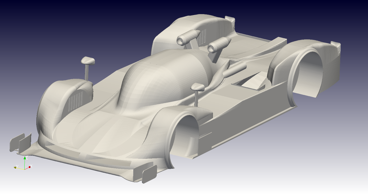
Base geometry containing a few holes in the stl file.
The geometry of this car contains a few gaps.
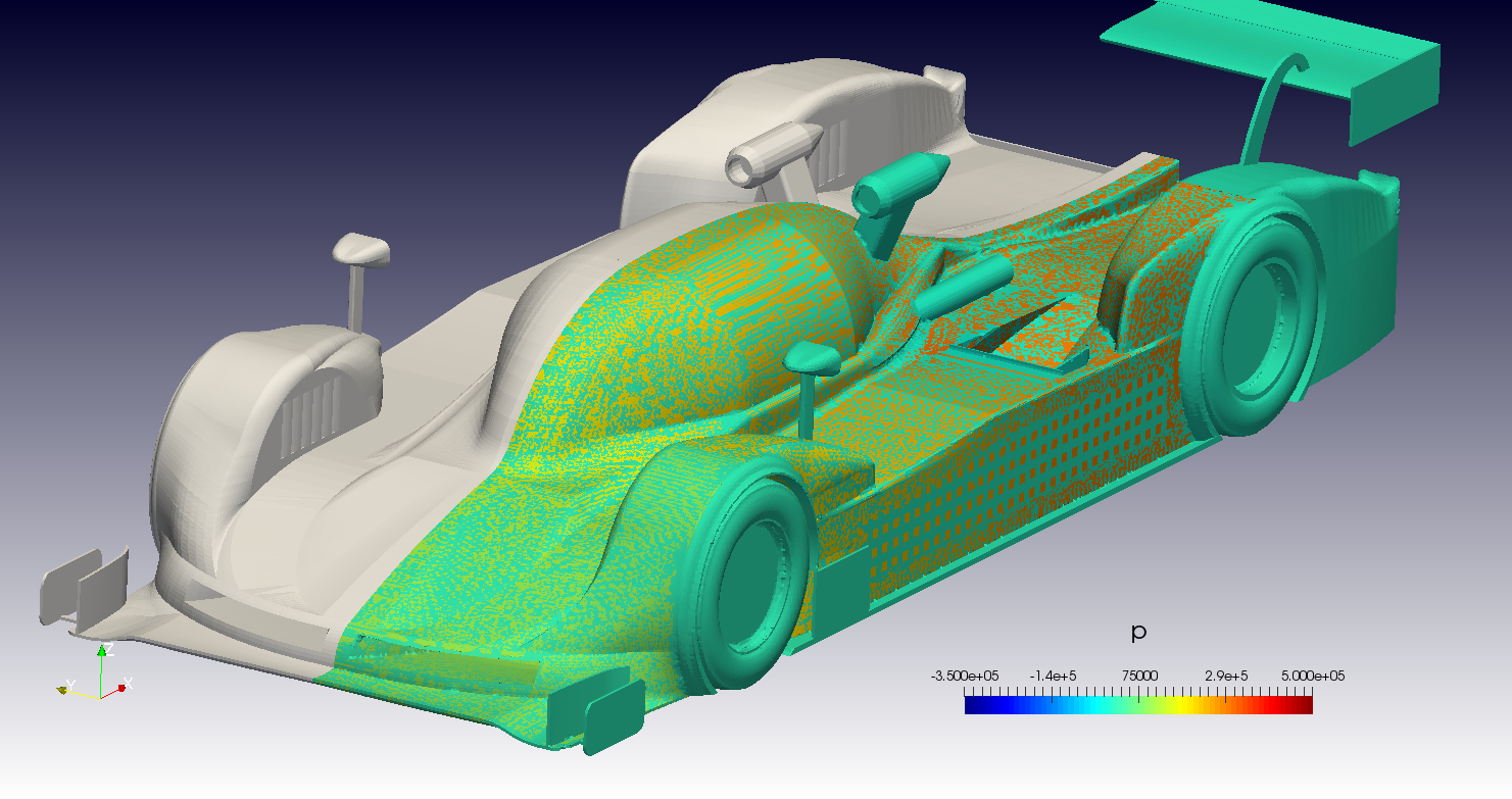
Often they can only be seen after the CFD simulation. Usually a checkerboard pattern can be seen when looking at flow properties like the pressure on the surfaces. These patterns are often because the post-processor does not know which side to show:
One method to find the location of the gaps and holes is to calculate the pressure gradient in the field. As the pressure inside of the car is often something strange to what is seen in the outside, the areas with the highest gradient might be where the holes are. Often it is a good idea to use the pressure from the potential flow solver used to initialize the CFD simulation for this. To calculate and visualize the areas of high gradients in Paraview, the following steps have to be taken:
First, with the case still selected in the Paraview pipeline, apply the filter Gradient Of Unstructured DataSet, then with the new item in the pipeline selected, use the Calculator filter to calculate the magnitude of the new vector filed Result (note the slide show arrows):
 1.) Calculate gradients

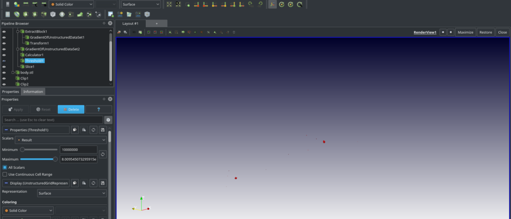
Now it is time to find the hop-spots by using a threshold on the previews Results. Select the Calculator result in the pipeline and apply a threshold. For the maximum, use the maximum value found in the field. With the minimum, you have to experiment until you find good values, only showing few locations in the field (note the slide show arrows):
 Threshold too small

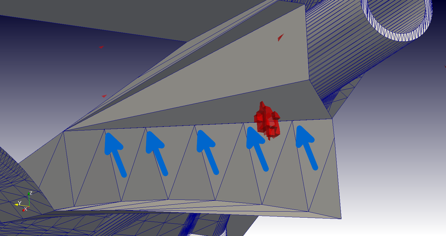
So we have identified a potential area of trouble. It is in one of the cooling ducts of this car. Looking at a velocity distribution clearly shows how some flow leaks to an area where it does not belong:

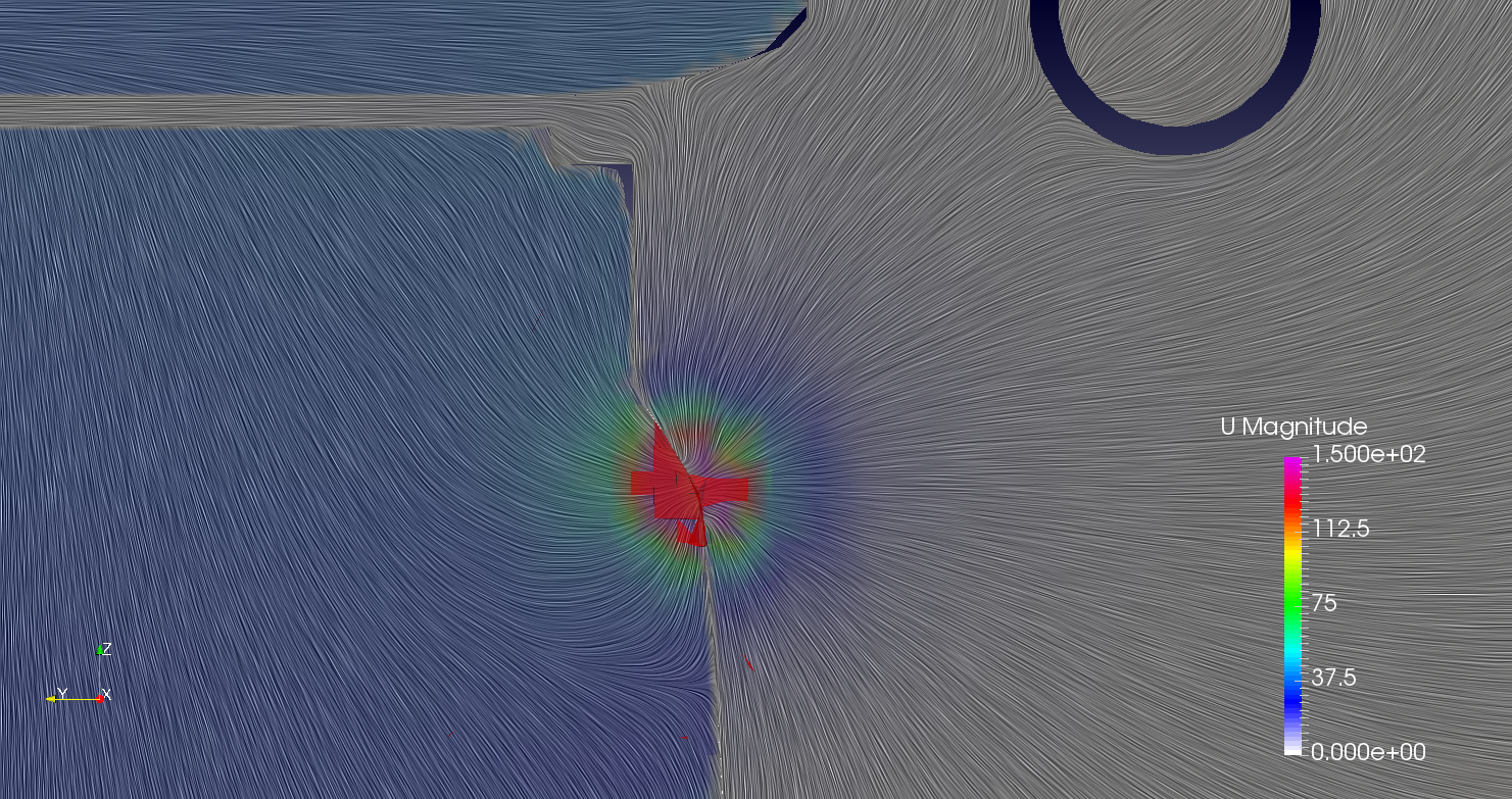
Only using a very high zoom factor reveals a small gap:
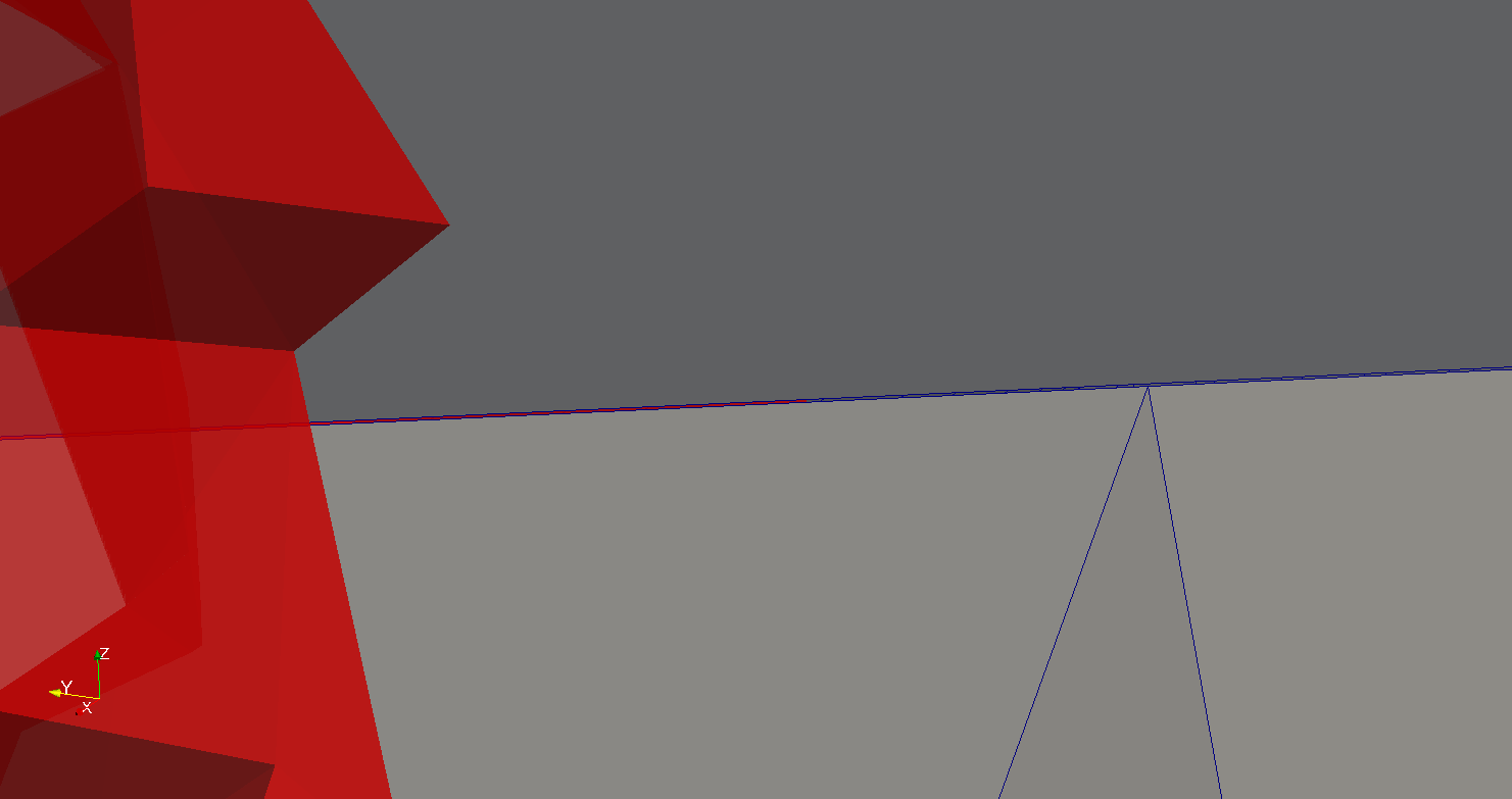
This one would have been hard to find by the inexperienced eye. A more experienced user might have noticed right away that the triangles of the stl do not align with upper part if the duct as there is only one large triangle along the whole length. This is often the reason for gaps in stl files.
MercuryMotorsport was not only nice enough to allow the usage of the images but also sent a script which helps with CAD cleanup when using Meshmixer:
Here are the provided instructions:
Meshlab Steps
File -> import mesh (Locate exported file of half the car)
Filters -> Show current filter script
Open Script (Locate script file in file browser)
Apply Script
Close dialog box
File -> Export Mesh As
Give a name and location and also change file type to *.stl
Save
un-tick Binary encoding and Materialise Color encoding
Save
Keep in mind that while automated scripts are always more than nice to have, a real CFD engineer has to always be able to perform manual CAD cleanup. In the case shown here, the issue will have to be fixed manually.
Well, have fun fixing your cars.

Sponsers MVRC 2017